


Advanced researchers are focusing on the synchronous calibration of DIC: measurement robustness and "automatic mesh generation" go hand in hand!
Release time:
2025-06-26 10:43
Source:
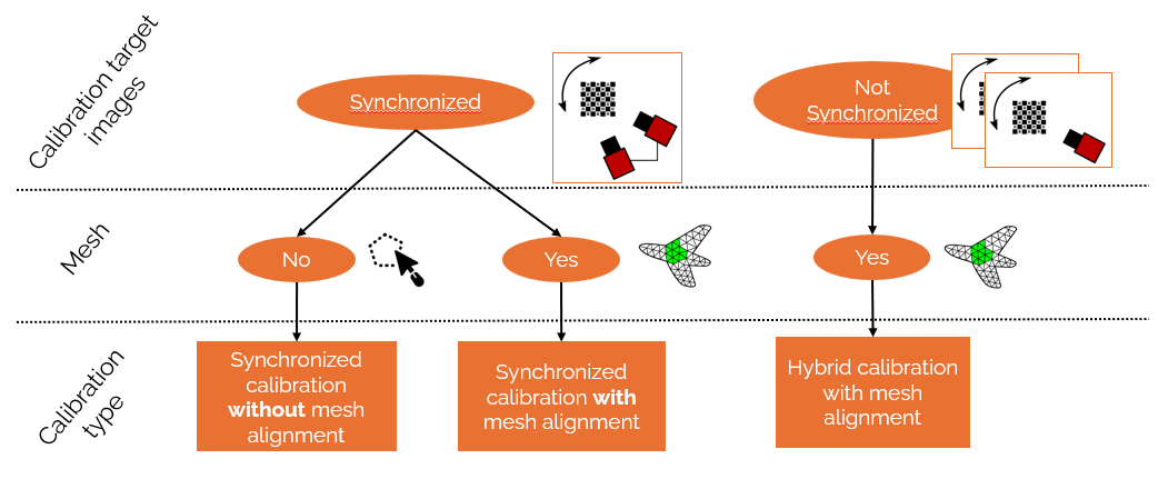
Today we will share with you how to perform calibration using synchronized target images (with or without grid alignment), a new procedure that can simultaneously determine intrinsic and extrinsic camera parameters.
This procedure is a complement to EikoTwin DIC 's existing hybrid method, which remains significant when camera synchronization cannot be achieved under experimental conditions. This article will introduce the basic principles of this synchronization method, its practical advantages, specific implementation steps, and the resulting workflow derived during mechanical testing with sensors.
Why is synchronized calibration needed during DIC measurements?
Synchronization of calibration target images ensures ideal geometric consistency between images captured by different cameras. This method is a strong complement to the existing hybrid calibration method in EikoTwin DIC EikoTwin DIC, especially in some test scenarios where synchronization cannot be achieved, the hybrid method still has practical value.
Using synchronized calibration offers the following advantages:
Enhanced calibration robustness: By maintaining fixed relative positions between cameras during test image acquisition, this method locks the relative pose between master and slave cameras, thereby reducing uncertain variables in the finite element (FE) mesh alignment process and effectively enhancing the stability of the entire digital image correlation (DIC) analysis workflow.
Improved measurement accuracy: Synchronized acquisition helps avoid measurement bias caused by difficulty in precisely estimating relative positions between cameras, especially when measuring grids close to a plane. This improves the quality of the external matrix and the overall accuracy of 3D reconstruction.
No need for finite element mesh alignment: When the experiment only requires displacement and strain measurement (rather than test-simulation comparison), this method can omit the pre-calibration step and directly define the measurement grid on the image, greatly simplifying the operation process. In simple scenarios, results can be obtained within 3 minutes.
Note: When using this method, the relative positions between cameras must remain unchanged from calibration shooting to test shooting. However, the entire camera system can be carefully moved as a whole for different test scenarios.
Operation process and recommendations
To ensure the accuracy and stability of synchronized calibration, strict operational specifications must be followed when acquiring calibration images. The recommended process is as follows:
Image acquisition preparation
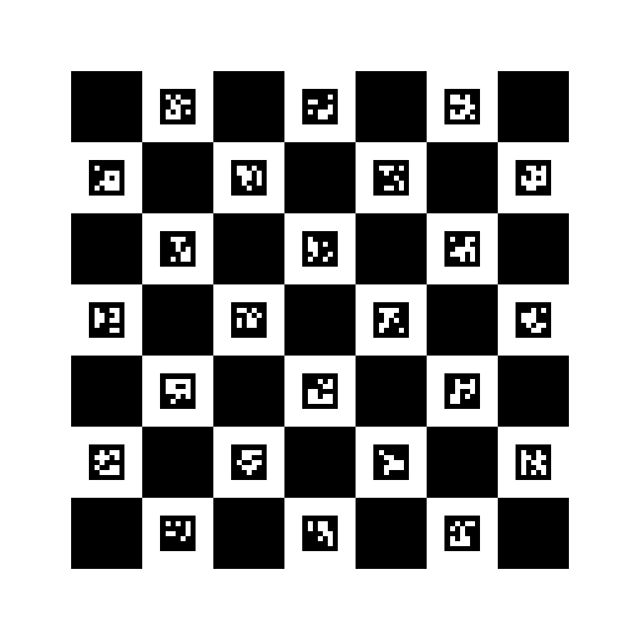
1. Use ChArUco calibration target:
EikoTwin DIC Use the ChArUco calibration target for camera calibration. Users can obtain it through EikoSim, use an existing calibration target, or purchase one on the calib.io platform.
The size of the calibration target should be matched and selected according to the actual camera's field of view and resolution.
2. Camera configuration
Optical setup: Depth of field must be sufficient to ensure the part remains in focus throughout the test.
Positioning: Firmly fix the relative positions of the cameras. After shooting calibration target images, no relative changes should be made unless a new calibration is performed.
3. Calibration target positioning and framing
The calibration target should occupy at least 50% of the image area, and its pattern must be clearly distinguishable.
Ideally, the calibration target should be placed at the location of the part to be tested, i.e., the actual position of the region of interest during testing.
If the depth of field is limited or the part is large, it is best to temporarily remove the part to position the calibration target or move the entire camera system.
4. Image quality check
Check image sharpness, overexposure, and reflections for each acquisition.
Ensure that at least 90% of the calibration board area is visible in a single acquisition to guarantee reliable detection of markers and corners.
5. Multi-angle image acquisition
Place the calibration target at the center of the stereo camera field of view.
Capture images at the following orientations:
▸ Zero rotation (calibration target plane parallel to image plane)
▸ Rotate ±20° around the vertical axis
▸ Rotate ±20° around the horizontal axis
6. Full field of view coverage calibration
Repeat the above operations at the four corners of the field of view to scan the 3D space covered by the cameras, ensuring calibration accuracy across the entire test area.
This process ensures the required image quality for processing and guarantees the reliability of calibration parameters estimated by EikoTwin DIC.
What if synchronization is not possible?
In some equipment or test constraints where camera synchronization is not allowed, the hybrid calibration procedure remains an effective alternative (right column of the first figure in this article).
This new calibration feature provides EikoTwin DIC users with two optional workflows:
◆ Option 1: Automatic grid generation
This process supports defining grids directly on images for 2D/3D displacement measurement without finite element model support.
➡️ No grid alignment needed, usable results can be obtained within 3 minutes, with very fast processing speed.
Limitation: Since no correspondence with the finite element model is established, test-simulation comparison analysis cannot be performed.
◆ Option 2: Measurement based on finite element mesh
Complete workflow suitable for scenarios requiring test-simulation comparison or working within the part's 3D coordinate system.
Includes:
Mesh alignment: Relocate camera poses in the 3D coordinate system through known points on the part within the mesh.
Final calibration: Optimize the projection matrix and update the finite element model shape to correct detected deviations.
Technical summary
EikoTwin DIC The newly introduced image synchronization calibration technology has the following advantages:
Significantly improves the accuracy and robustness of measurement tasks
Simplifies the implementation process in synchronous configurations
Provides two differentiated solutions:
▶ Rapid implementation automatic mesh solution (pure measurement scenarios)
▶ Standard process supporting finite element mesh alignment (essential for deep analysis/simulation recalibration), enabling higher repeatability and robustness in calibration
EikoTwin DIC,Non-contact strain measurement,Synchronous Calibration of DIC,Robustness of DIC Measurement