


MBD model quality inspection process and tool application plan in intelligent manufacturing, would you like to learn more about it?
Release time:
2025-07-15 13:57
Source:
Introduction
In today's rapidly developing industrial manufacturing field, the application of Model-Based Definition (MBD) technology has become an important means for enterprises to improve efficiency and quality. However, this brings about the necessity of model quality inspection processes and tools. Once the model quality is substandard, subsequent production and design may face numerous difficulties.
The Rise of MBD Technology
MBD technology greatly simplifies traditional workflows by embedding design, manufacturing, and quality inspection information into 3D models. The promotion of this technology enables designers and engineers to collaborate on a unified platform, thereby improving product development efficiency. However, in this process, model quality becomes particularly important.
Challenges of Model Quality
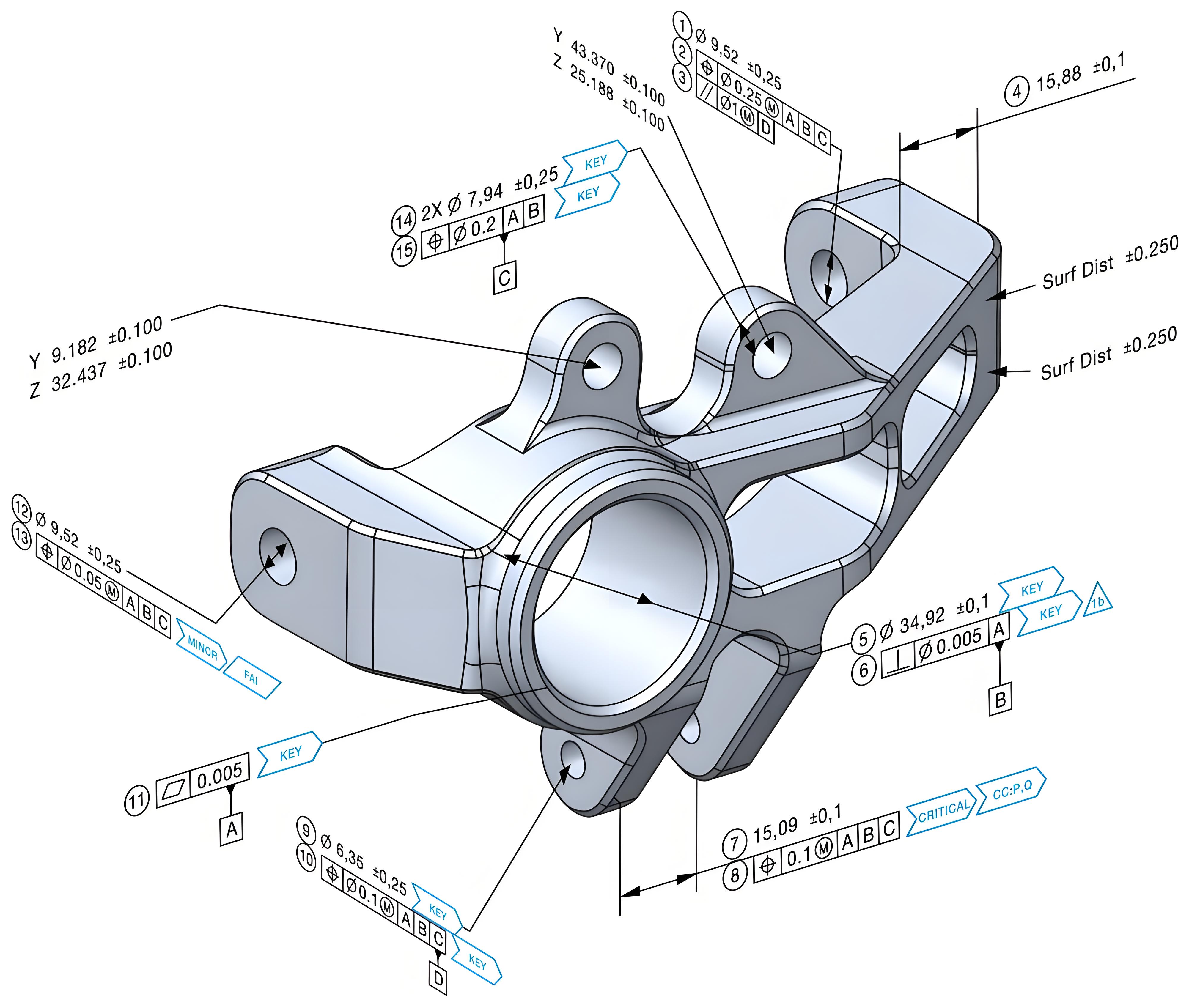
In the MBD (Model-Based Definition) workflow, ensuring the quality of the 3D model as the sole authoritative data source faces a series of complex and interrelated challenges. The primary challenge lies in data integrity and semantic clarity: the model must accurately carry all product definition information (GD&T, annotations, material specifications, process requirements, BOM, etc.), ensuring that these PMIs (Product Manufacturing Information) are not only geometrically correct but also semantically clear and unambiguous within the model's tree structure. They must be accurately interpreted by downstream systems (such as CAM, CMM, assembly simulation) to avoid misunderstandings caused by ambiguous annotations or missing context. Secondly, model robustness and downstream interoperability are core difficulties: the model must maintain geometric stability, preserving feature associations even after modifications, avoiding regeneration failures or PMI invalidation; meanwhile, data exchange between different CAD systems (such as STEP 242) often suffers from information loss or distortion due to software support differences or incomplete PMI mapping, especially when handling complex tolerance stacks or surface annotations. Furthermore, process standardization and personnel capability form key bottlenecks: enterprises need to establish and enforce unified MBD modeling, annotation, and review standards (such as ASME Y14.41-2019), but differences in standard interpretation, legacy drawing habits, and varying model information needs across departments (design/process/manufacturing/quality) can cause information redundancy or omission; engineers must be proficient in 3D design, GD&T, manufacturing processes, and software applications, and cultivating such multidisciplinary talents takes a long time. Finally, version control and change management become more complex in a pure model environment: minor model changes may have cascading effects on associated PMIs, requiring strict tracking of change impact domains and ensuring all users receive updated versions in real time, posing high demands on PLM systems. These challenges collectively point to a core truth: MBD is not just a technological upgrade but a paradigm shift in design and manufacturing, requiring systematic coordination of technology, processes, standards, and talent to ensure model quality truly supports a fully digital workflow.
The Importance of Model Quality Inspection Processes and Tool Applications
To ensure model quality, enterprises must establish a complete set of model quality inspection processes and model quality management tools. This not only improves model accuracy but also reduces time and cost for later modifications.
1) Design Phase Check (Pre-release Check) After the designer completes the model, an initial validation is immediately conducted. Key points include: geometric feature integrity (no broken surfaces, no unclosed solids), compliance of basic PMI (Product Manufacturing Information) annotations (in accordance with ASME Y14.41-2019 or ISO 16792 standards) [1], and clarity of the model tree structure. At this stage, built-in MBD plugins in CAD systems (such as Siemens NX PMI Advisor, PTC Creo MBD Advisor, Dassault Systèmes 3DEXPERIENCE MBD workflow) can be used for real-time rule checking to quickly capture low-level errors.
Standardization & Semantic Validation: Performed by dedicated MBD engineers or quality personnel. Based on the enterprise's customized MBD modeling specifications (usually based on ASME Y14.45-2021), a deep review is conducted: semantic correctness of GD&T annotations (datum reference chains, application of tolerance principles), logical organization of PMI views, association between annotations and model features, and consistency of BOM data. This stage is critical to ensure downstream understandability.
2) Downstream Compatibility Check Simulating actual application scenarios. The model and PMI are exported to neutral formats (such as STEP AP242), for example, using CAPVIDIA MBDVidia software for validation. MBDVidia excels at parsing CAD model files, checking whether PMI information is fully retained, whether the association between geometry and annotations is correct, and whether tolerance data can be accurately recognized by CMM or CAM systems [2], effectively preventing information loss during data exchange.
3) Manufacturing Review A joint review involving process, tooling, and quality engineers. Using the model for virtual assembly, tolerance stack-up analysis, and manufacturability assessment to ensure that the tolerances and process requirements defined by PMI are practically feasible and cost-effective. PUNDIT can directly read GD&T from MBD models, perform 3D tolerance simulation, predict potential quality risks in the model, and evaluate uncertainties in CMM measurement plans.
4) Change Impact Analysis When the model is revised, the CAPVIDIA CompareVidia tool is used for intelligent comparison. This tool goes beyond simple geometric differences, accurately identifying additions, deletions, and modifications of PMI annotations (tolerance values, datums, annotation texts), visualizing annotation change locations, greatly improving the efficiency and accuracy of change reviews and avoiding missing critical modifications.
Recommended Tools
1) 3D Design and Annotation Tools
The starting point of MBD is 3D CAD modeling. Mainstream tools such as SolidWorks, CATIA, NX, Creo, etc., all support PMI annotations, allowing engineers to directly define geometric tolerances (GD&T), surface roughness, and other manufacturing information on the model. However, data interoperability between different CAD systems remains an industry challenge, especially when the supply chain involves multiple software packages, making accurate transmission of model information crucial. MBDVIDIA supports PMI data conversion between mainstream CAD systems, and its technology has been certified by NIST. Its application in the aerospace field has shown significant reduction in data loss issues.
2) Simulation and Verification Tools
MBD models are not only used for design but also need to be verified for manufacturability through simulation. For example:
- Structural simulation (ANSYS, Altair HyperWorks)
- Tolerance analysis (3DCS, CETOL)
- System simulation (MATLAB/Simulink)
However, simulation tools usually rely on high-quality data input. If GD&T information in the MBD model is lost or incorrect, it may lead to biased analysis results. COMPAREVIDIA provides 3D model difference analysis, visually displaying geometric and PMI changes between versions to ensure the high quality and reliability of MBD models.
3) Manufacturing and Inspection Execution
The ultimate goal of MBD is to guide production, so CAM (Computer-Aided Manufacturing) and CMM (Coordinate Measuring Machine) must accurately read the manufacturing requirements in the model. For example:
- CNC machining (Mastercam, PowerMill)
- 3D printing (Materialize Magics)
- Quality inspection (Hexagon PC-DMIS, Zeiss CALYPSO)
However, many manufacturing companies have reported that due to data compatibility issues between different systems, CMM equipment may not correctly recognize the GD&T in MBD models, resulting in low inspection efficiency.
MBDVIDIA software can help companies obtain truly human- and machine-readable MBD models, solving data compatibility problems. MBDVDIA can generate QIF format models, a data format recommended by the National Institute of Standards and Technology (NIST) in the United States. It can establish seamless connections between CAD, CAM, and CMM, ensuring precise execution of MBD requirements in manufacturing and inspection processes. According to statistics, companies using QIF can improve inspection efficiency by more than 30% and reduce error rates by 50%. Meanwhile, PUNDI software helps companies evaluate the uncertainty of inspection plans through simulation, ultimately providing the optimal inspection plan.
Conclusion
In summary, the model quality inspection process and tools are indispensable in the application of MBD technology. If industrial manufacturing companies pay attention to this process, they can not only improve product quality but also gain an advantage in the fierce market competition. As a wise person once said: "Prevention is better than cure." Strictly controlling quality during the design phase is the key to the long-term development of enterprises.
Model Quality Inspection Process and Tools,MBD Model Quality Management,MBD Workflow,PMI Inspection