


Exploring the Application of Grid-Based DIC Strain Measurement Equipment in Automotive Collision Safety Analysis
Release time:
2025-06-05 11:25
Source:
Today, let's explore the key applications of grid model-based DIC (Digital Image Correlation) strain measurement equipment in automotive crash safety analysis. This technology is increasingly becoming the indispensable "eyes" of crash test laboratories because it reveals complex deformation information that traditional sensors find difficult to capture.
1. Technical Principles
The grid model-based DIC (Digital Image Correlation) strain measurement system is an advanced technology combining CAD grid models with digital image correlation algorithms. Its core principle is to achieve high-precision full-field strain analysis by directly correlating the 3D grid model of the tested object with image sequences. The basic principles and technical features are as follows:
1) Core Principle
Image Correlation and Displacement Tracking
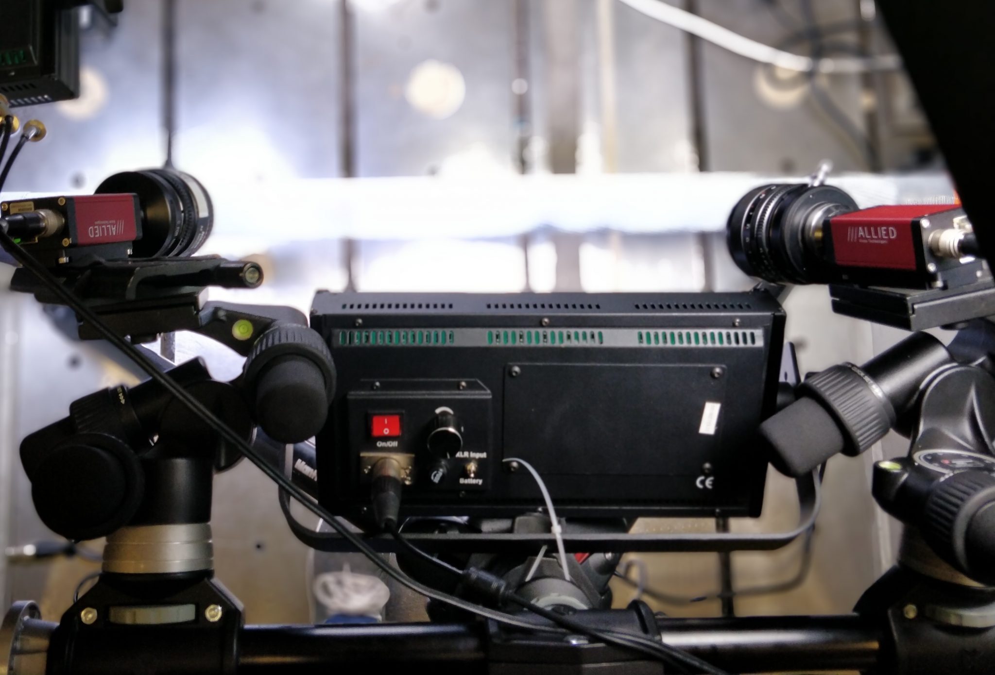
The system uses multiple cameras to capture sequential images of the object's surface during deformation in real time. It employs digital image correlation algorithms (DIC) to track displacement changes of surface feature points (such as natural textures, artificially sprayed speckles, or grid nodes). The algorithm calculates the 2D or 3D displacement vectors of each feature point by matching image subsets before and after deformation.
Grid Model as the Computational Reference
Unlike traditional DIC (which uses the image plane as a reference), grid model-based DIC directly uses the CAD grid model (MESH file) of the tested object as the spatial coordinate system. The algorithm maps the collected image data onto the grid model nodes and calculates displacement and strain fields directly on the grid surface. This correlation avoids coordinate reconstruction errors and allows data to be directly compared with simulation models (such as FEM).
Full-field Strain Calculation
By densely tracking displacement data of grid nodes and combining continuum mechanics theories (such as the Green-Lagrange strain tensor), the system calculates the full-field strain distribution on the object's surface (including principal strains, shear strains, etc.).
2) Technical Features
Integration of Simulation and Experimental Data
The grid model usually matches the geometric structure of finite element simulations (FEM), enabling experimental strain field measurements to be directly used for simulation model validation and parameter calibration (such as material constitutive parameters and boundary conditions), significantly improving simulation accuracy.
Suitability for Complex Structures
The system supports multi-camera collaboration and automatically stitches multi-view data through marker points, achieving full-field coverage of large or curved structures. It is suitable for measurement needs in extreme environments such as high temperature and high pressure.
Error Control Advantages
Geometric Consistency: The grid model avoids errors caused by simplified geometry (such as thin-wall thickness differences) in traditional DIC.
Boundary Condition Optimization: Directly correlates with actual structural boundaries, reducing model deviations caused by inaccurate boundary assumptions in traditional methods.
2. Core Applications in Automotive Crash Safety Analysis
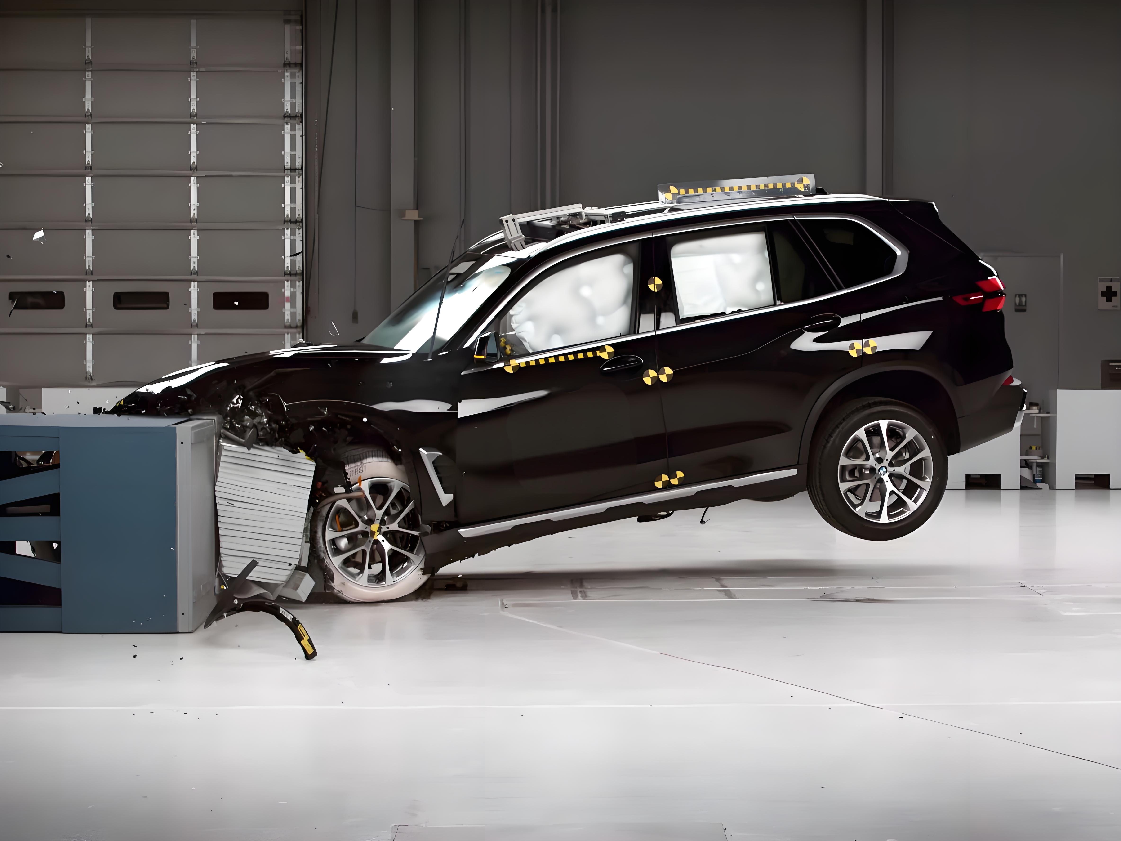
Grid model-based DIC technology brings revolutionary insights to crash safety analysis, mainly reflected in the following aspects:
Full-field Deformation Visualization and Quantification
Beyond Point Measurement: Completely replaces or greatly supplements traditional strain gauges (which can only measure local points), displacement sensors (measuring displacement at specific points), and accelerometers (measuring acceleration at specific points), providing continuous deformation and strain distribution maps of the entire tested surface.
Intuitive Display: Engineers can visually see how deformation occurs, propagates, and concentrates. For example, clearly observing the buckling waveform of the B-pillar, bending locations of door anti-collision beams, crushing modes of longitudinal beams, intrusion paths of the front bulkhead, etc. Color cloud maps clearly mark high strain areas (red/yellow) and low strain areas (blue/green).
Identification of Key Failure Locations and Modes:
Material Failure Analysis: Precisely identifies locations where materials reach ultimate strain (fracture strain), which is crucial for understanding failures such as sheet metal cracking, high-strength steel fracture, and composite interlaminar delamination. DIC can capture failure initiation points and propagation paths.
Structural Failure Analysis: Identifies buckling initiation points (local instability), plastic hinge formation locations, and failures at connection points (welds, rivets, adhesives). The grid model clearly shows the formation process of local wrinkles and dents.
Validation and Optimization of CAE Simulation Models:
Gold Standard Data Source: The full-field displacement and strain data provided by DIC are the most direct and rich experimental basis for validating computer-aided engineering (CAE) crash simulation models (such as LS-DYNA, RADIOSS, Abaqus, etc.).
Improving Model Accuracy: By comparing DIC measured results with simulation predictions (displacement fields, strain fields, deformation patterns), engineers can identify deficiencies in material constitutive models, failure criteria, contact definitions, and connector modeling, and perform targeted corrections and optimizations, significantly enhancing simulation prediction accuracy and reliability. Grid model data can be directly compared point-to-point or region-to-region with simulation model output grid node data.
Evaluation of Occupant Protection Related Structural Performance:
Occupant Compartment Integrity: Accurately measures intrusion amount, intrusion speed, and deformation patterns in key areas such as pedals, steering wheel, A-pillar, sill beam, and floor, directly relating to driver and passenger survival space and lower limb injury risk.
Restraint System Action Points: Measures deformation in areas such as seatbelt anchor points and airbag brackets, assessing the effectiveness and potential failure risks of restraint systems during collisions.
Dummy-Interior Interaction: Can be used to measure deformation and strain of interior panels (such as dashboards and door trims) in dummy collision contact areas, evaluating impacts on dummy head, chest, knees, and other parts.
Material Characterization (Especially under Dynamic Large Deformation):
Although usually conducted on material testing machines, DIC can also indirectly provide information on material deformation behavior under actual high-speed impact and complex stress states (such as shear, tensile-bending combinations) during crash tests, offering valuable references for understanding material performance in full vehicle crash environments.
Optimization of Structural and Material Design:
Based on the deformation and failure mechanisms revealed by DIC, engineers can purposefully optimize structural geometry (such as stiffeners, induced groove design), material selection (positions for using steels of different strength grades, aluminum alloys, composites), material thickness distribution, connection methods, etc., to improve the structure's energy absorption efficiency, control deformation modes, avoid unexpected failures, and ultimately enhance the vehicle's crash safety performance.
3. Advantages (Why is it particularly valuable in collisions?)
Non-contact: No need to install sensor wires on the specimen, avoiding issues of wire breakage or interference during severe collisions, and suitable for harsh environments such as high temperature and high speed.
Full-field measurement: Provides continuous, high spatial resolution displacement and strain information, revealing global and local deformations.
High dynamic range: High-speed cameras and powerful algorithms can capture intense deformations occurring within milliseconds.
Three-dimensional information: Provides in-plane and out-of-plane displacements, comprehensively describing deformation.
Wide applicability: Can measure various materials (metals, plastics, composites) and structures of various sizes (from local small parts to the entire vehicle body-in-white).
Provides abundant data: Offers massive data support for CAE validation and in-depth failure analysis.
4. Conclusion
Mesh-based DIC strain measurement equipment has become one of the core tools in modern automotive crash safety analysis laboratories. By providing high-resolution, full-field, three-dimensional dynamic deformation and strain data, it greatly deepens engineers' understanding of structural behavior, material failure, and energy absorption mechanisms during collisions. This valuable data is key to validating and optimizing CAE simulation models, directly driving the design of safer and lighter automotive structures. Despite challenges in cost and technical complexity, the profound insights and contributions to safety performance improvements have made it increasingly important in the field of automotive passive safety R&D. It allows engineers to "see" the invisible forces and deformations during collisions, serving as an indispensable "sharp eye" for enhancing vehicle safety performance.
If you are interested in the application of DIC on a specific component (such as battery pack collisions), or its combined use with other technologies like high-speed photography/X-ray, further discussion can be pursued.
Automobile Collision Safety Analysis,DIC Based on Grid Model,Non-contact strain measurement