


Exploring the Application Prospects of DIC Strain Measurement Equipment in White Body Stiffness Testing
Release time:
2025-06-04 10:53
Source:
Introduction: The Importance of White Body Stiffness Testing
In the automotive manufacturing industry, White Body Stiffness Testing is a crucial step in evaluating the structural strength and safety of vehicles. With technological advancements, traditional testing methods are gradually being replaced by more efficient and precise techniques. Today, let's discuss the grid model-based DIC (Digital Image Correlation) strain measurement equipment and its applications across various fields.
What is DIC Strain Measurement Equipment?
DIC strain measurement equipment is an advanced tool that uses image processing technology to obtain deformation information on the surface of objects. It captures the target with high-resolution cameras and analyzes image changes through software to acquire strain data. This method is not only fast but also enables non-contact measurement, ensuring accuracy and safety during testing.
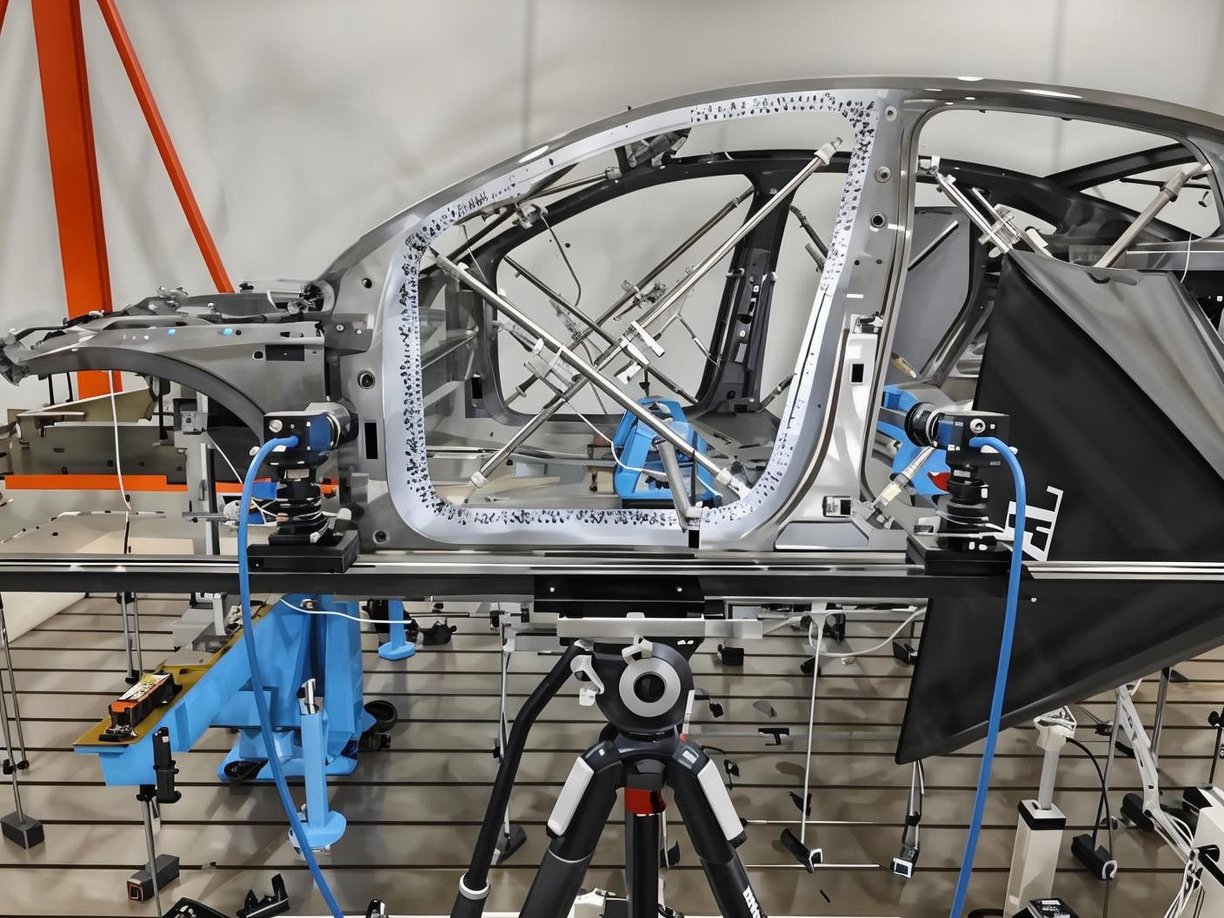
Applications of White Body Stiffness Testing
So, how exactly is the grid model-based DIC strain measurement equipment applied to White Body Stiffness Testing ? Next, we will explain in detail one by one:
Core Application Process:
Preparation and Grid Creation:
Surface Treatment: Clean the white body surface to ensure it is free of oil, dust, and reflective coatings (such as clear varnish). Usually, a matte primer (such as matte white paint) is sprayed to enhance surface contrast and diffuse reflection characteristics.
Grid Creation: Spray a high-contrast random speckle or grid pattern on the test area (usually key joints, longitudinal beams, cross beams, sills, A/B/C pillars, door frame openings, etc.). The quality of the pattern (size, density, contrast, randomness) directly affects the measurement accuracy of DIC.
Equipment Installation and Calibration:
Camera Setup: Securely mount two or more high-resolution, high-frame-rate digital cameras (usually industrial-grade CCD or CMOS cameras) on rigid tripods or brackets to cover the entire test area. Camera positions and angles must be precisely set according to the size of the object and the required field of view.
Lighting Arrangement: Install a uniform and stable lighting system (such as LED arrays) to eliminate shadows and ensure even illumination across the measurement area, reducing ambient light interference.
System Calibration: Use a precision calibration plate (with known dimensions and patterns) moved within the measurement space for the cameras to capture from different angles; or pre-set the experimental environment in a virtual setting and then calibrate on the grid model to ensure efficient experimentation.
Test Execution and Data Acquisition:
Loading Device: Mount the white body on the test rig according to testing standards (such as bending stiffness and torsional stiffness tests).
Synchronization: Synchronize the DIC system with the test machine control system. Ensure the DIC cameras capture images at a set frequency (e.g., several frames per second) during loading (usually quasi-static loading).
Reference Images: Capture reference images before loading (zero load state).
Loading and Acquisition: Start the test machine and apply loads (bending or torsion) to the white body according to the preset loading curve (force or displacement control). The DIC system continuously and synchronously captures image sequences during loading.
Data Processing and Analysis:
Image Correlation Calculation: The DIC software processes the captured image sequences. By comparing the grayscale distribution changes in each small region (subset) between the current image and the reference image (and adjacent images), it uses correlation algorithms (such as normalized cross-correlation) to calculate the displacement vector of each subset in 3D space.
Displacement Field Calculation: The software calculates 3D displacement data (Ux, Uy, Uz) for thousands of points within the measurement area.
Strain Field Calculation: Based on displacement data of adjacent points, numerical differentiation (such as Green-Lagrange strain tensor calculation) is used to obtain the full-field strain distribution (engineering strain or true strain, such as εxx, εyy, εxy, principal strains, etc.).
Visualization: Displacement and strain results are intuitively displayed on the body model as cloud maps, vector diagrams, deformation animations, etc. Key points (such as sensor simulation points, maximum strain points) displacement-time and strain-time curves can be extracted. The grid model-based DIC can directly display strain measurement results on the grid model, allowing direct comparison between FEM results and actual measurements, which is very intuitive.
Stiffness Calculation:
Bending Stiffness: In bending tests, DIC can directly measure the vertical displacement of the sill beam or longitudinal beam at specific locations (usually corresponding to loading or support points). Combined with the load measured by the test machine, bending stiffness (load/displacement) can be calculated. The advantage of DIC is that it can measure displacements at multiple points to assess the overall bending deformation pattern and uniformity of the body.
Torsional Stiffness: In torsion tests, DIC can directly measure the relative rotation angle of the front and rear ends of the body (such as the cross beam under the front windshield and the rear end of the rear longitudinal beam) after applying torque. The software calculates relative displacements between key points and converts them into angular changes. Combined with the torque measured by the test machine, torsional stiffness (torque/angle) can be calculated. DIC accurately captures the overall torsional deformation of the body, avoiding measurement errors caused by installation inaccuracies.
Unique Advantages of DIC in White Body Stiffness Testing:
Full-field Measurement: Provides displacement and strain distribution over the entire measured surface, rather than single-point data from traditional sensors (strain gauges, LVDTs). This helps to:
Comprehensively Understand Deformation Behavior: Visually identify stress concentration areas, deformation patterns, and load transfer paths.
Detect Potential Issues: Identify design or manufacturing defects (such as local yielding, weld joint failure, design weak points).
Validate CAE Models: Provide massive full-field data points for high-precision, high-spatial-resolution comparison and validation against finite element analysis results.
Non-contact: No need to paste a large number of strain gauges or install displacement sensors on the vehicle body, avoiding interference with the tested structure (such as increased mass, local stiffness changes), and greatly simplifying test preparation (especially for complex curved surfaces).
High spatial resolution: Able to capture very local strain gradients and tiny deformations, which is crucial for identifying stress concentration points and optimizing local structures.
Measurement flexibility: Can measure complex curved surfaces and hard-to-reach areas (such as deep cavities, narrow spaces nearby), not limited by sensor wiring.
3D displacement/strain: Simultaneously measures in-plane (X, Y) and out-of-plane (Z) displacement and strain, providing complete deformation information. This is especially important when analyzing complex deformations such as torsion and buckling.
Measurement of large deformations: Capable of accurately measuring the entire process from small elastic deformations to large plastic deformations.
Simplified torsion angle measurement: Directly calculates the relative torsion angle of key points before and after through images, more direct and accurate than traditional methods (such as laser rangefinders, inclinometers), and not affected by installation parallelism and other factors.
Rich data: Provides data volume far exceeding traditional methods, supporting deeper analysis and optimization.
Challenges and considerations:
Equipment cost: DIC systems (cameras, lenses, software) are usually more expensive than traditional sensor systems.
Computing resources: Processing massive image data requires powerful computer hardware and longer computation time (especially for high resolution and long-duration tests).
Surface preparation: Speckle/grid creation requires time and skill, and quality directly affects results.
Environmental requirements: Sensitive to vibration and changes in ambient light, requiring a stable testing environment. Strong light, shadows, smoke, etc., can affect image quality.
Calibration accuracy: The accuracy of calibration is the foundation of the entire measurement accuracy and must be performed rigorously.
Data processing complexity: Requires professional software and operators to correctly set parameters, process data, and interpret results.
Dynamic measurement limitations: High-speed dynamic events (such as collisions) require cameras with extremely high frame rates, greatly increasing cost and technical difficulty.
Summary :
The grid-based DIC strain measurement equipment provides unprecedented testing capabilities and insights in white body stiffness testing through non-contact full-field 3D displacement and strain measurement. It can not only accurately calculate bending and torsional stiffness but also visually display the full-field deformation behavior of the body under load, identify stress concentration areas, validate simulation models, and greatly simplify the measurement process of key deformation quantities (especially torsion angles). Despite challenges such as cost, computation, and environmental requirements, the rich information and efficiency improvements it brings make it an indispensable powerful tool in modern automotive R&D and quality control, especially in body structure optimization and CAE validation stages, gradually becoming one of the advanced standard methods in the stiffness testing field.
White body stiffness test,DIC Strain Measurement