


DIC Experiment - Application of Digital Image Correlation Technology in Crack Measurement
Release time:
2022-05-17 15:00
Source:
The EikoTwin image correlation measurement scheme has been successfully applied to crack propagation tests in composite materials, fully meeting the client's needs. To ensure client satisfaction, EikoSim specially customized a measurement scheme: developed a post-processing script to effectively utilize the measurement data from EikoTwin DIC.
Paul Nicolino graduated from the mechanical engineering program at INSA Lyon in 2021, and the measurement scheme mentioned above was part of his engineering internship at EikoSim.

Standardized testing and traditional measurement methods
In the aerospace industry, a thorough understanding of the fracture behavior of materials used in mechanical part design is essential. In practical cases of crack propagation, there are three crack modes (I, II, and III, see below).

To study specific crack modes, several types of tests can be chosen. In this experimental work, we only selected the DCB (Double Cantilever Beam) test—this is a commonly used test type in experiments because it fully reflects mode 1 cracks.

According to the ISO 25217 standard used in this project ("Determination of mode 1 adhesive fracture energy of structural adhesive joints using double cantilever beam [...] specimens"), one side of the specimen remains free (right end in the figure and in the image below). Crack propagation is generated by applying vertical forces on each arm through a rotary joint mounted on a pulling machine.

Knowing the length of the crack during the DCB test allows for the determination of the critical energy release rate in mode I, note:

Physically, the energy release rate corresponds to the energy released by the crack to advance one unit of surface. Therefore, this quantity can quantify the material's ability to resist crack propagation (sometimes referred to as toughness).
The first experimental method for measuring crack length is to use a gauge placed in the crack area, which gets cut one by one as the crack propagates. The main disadvantage of this method is that it only provides discrete results of crack propagation during the test, with relatively few measurement points, leading to longer experimental times.
Another commonly used measurement method is to obtain test images, where a white-coated specimen is placed against a black background to clearly distinguish the crack. Then, during the test, the pixels at the crack tip are manually located, allowing for the determination of the crack length on each image by understanding the physical size of the pixels.
This approach has several drawbacks. First, manually plotting the pixel positions of the crack tips in each image is both cumbersome and time-consuming. It seems impossible to perform crack tracking in about a dozen tests, each containing hundreds of images. On the other hand, the risk of error and measurement uncertainty cannot be ignored. There is also the subjectivity of measurement, which depends on the operator's attention to the pixel positions.

In this case, Safran Aircraft Engines expressed a willingness to improve its DCB testing procedure, hoping to measure the crack length automatically through image correlation for each test. This is the technical solution developed and proposed by EikoSim, especially using digital image correlation.EikoTwin DIC softwareThe principle of digital image correlation
Digital image correlation is a measurement method that uses camera images to track the displacement and deformation of solids during motion, such as crack propagation. It is commonly used to track and utilize physical tests in research and the mechanical industry, as well as in a variety of applications, from material specimens to 'subsystem' specimens (bolt assemblies, technical parts), and even very large structures (parts of aircraft or helicopters, road or railway bridges, and nuclear structures). Its advantages include being non-destructive, non-contact, and applicable regardless of the material or shape of the observed structure, provided that the area of interest can be captured by the camera.
In this project, the testing scheme will use a single camera, so we will focus only on 2D-DIC.
DIC mainly compares two digital images of the structure taken by a single camera at two different deformation moments, known as the 'reference' moment and the 'deformed' moment. Through this comparison, a two-dimensional displacement field at the motion origin between these two moments can be obtained across the entire surface visible to the camera. To ensure the convergence of the DIC algorithm, especially to observe the different deformation states experienced by the part throughout the test, we cannot settle for images taken before and after the test. A set of intermediate images must be captured, and comparisons must be made sequentially between all images referred to as 'deformed' and the initial image referred to as 'reference'.
The basic principle of image correlation technology is based on the assumption that the gray distribution of an image remains unchanged when undistorted. Ultimately, it is the gray distribution characteristics of the thumbnails that distinguish them from other thumbnails; therefore, the importance of sufficiently random speckle is to ensure that the gray distribution of each thumbnail is unique. As the speckles follow the material's motion, to respect the previous gray conservation assumption, the speckle grid will deform with the part.

These principles briefly summarize the technology behind EIKODIC. Please refer to other blog posts for more details:

Application of image correlation in DCB crack propagation tests
- Safran Aircraft Engines and EikoSim jointly demonstrated
- a perfect example of using Eikostwin DIC software for standardized mechanical testing.
- According to the software method, after importing the test images and selecting the measurement grid, pre-calibration is performed to align the measurement grid with the reference image.
- Then, we can proceed to the 'displacement' step, where the software measures the displacement at each time step using a series of images loaded in each camera. Here we can observe the vertical displacement field of the given image.
The correlation residual field can also be visualized. These residuals provide information about the quality of the calculations and also allow for the visualization of crack progression after image correlation measurements.
To obtain the best possible measurement data, we recommend adopting some good practices for such tests:• Check the consistency between the digital model and the actual sample (same dimensions, same spatial orientation, etc.).• Set the camera frame to view the sample length related to the length you wish to measure.
根据软件方法,导入测试图像并选择测量网格后,执行预校准,以将测量网格与参考图像对齐。

然后,我们可以进入“位移”步骤,软件使用每个摄像头中加载的一系列图像测量每个时间步的位移。这里我们可以观察给定图像的垂直位移场。

还可以可视化相关残差场。这些残差提供了有关计算质量的信息,还允许在图像相关测量后可视化裂纹的进展。

为了尽可能获得最佳的测量数据,我们建议对此类测试采取一些良好的做法:
•检查数字模型和实际样本之间的一致性(相同的尺寸、相同的空间方向等)。
•设置摄像头的框架,以查看与您希望测量的长度相关的样本长度。
• Create spots related to images and sample sizes.
• Set a solid color background different from the sample.
• Check the lighting: the brightness of the entire sample must be uniform (no shadows or reflections), and it must be clearly distinguishable from the background. Although the sample may move during the test, changes in brightness should be minimized.
• Take a series of images without applying motion to determine measurement uncertainty ("noise floor").
To determine the ideal spot size for the sample, we provide a spreadsheet on the website.
Advance the crack tip with a post-processing script.
Once the study is complete, DIC can export displacement and strain results as .csv files. This feature is particularly useful in this project for determining crack propagation during DCB tests.
The solution developed here is a Python post-processing script designed according to the requirements of Safran aircraft engines, which determines the crack length during DCB tests by utilizing data exported from EikoTwin DIC. It works as follows:
• First, it must useEikoTwin DIC softwareto conduct experimental research to export the displacement data of the sample.

• After completing the displacement field calculation using DIC, the displacement data will be exported.
• The data is organized as follows: each image is associated with a .csv file that contains the displacement and the position of each node in the measurement grid along X, Y, and Z.

• Before running the script, the user specifies the values of two vertical coordinates

to select two rows of nodes on either side of the interface.
• Thus, nodes with equal horizontal coordinates are paired. For each pair and each frame, the script will determine the difference in vertical displacement:


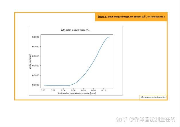
• Obtain the vertical displacement difference for each pair of nodes in each frame.
• For each frame, when the vertical displacement difference reaches the crack opening criterion*, the corresponding horizontal position is recorded.
*The script considers that a crack opening occurs when the relative vertical displacement between the two nodes of the same pair exceeds 0.1 mm:

The value of 0.1 mm was chosen based on the uncertainty of downward displacement measurements from DIC.

By repeating the previous operations for each image, the horizontal positions where the crack opening criterion is met throughout the test are determined. In other words, we determine the crack length during the test.

• At the end of the script, the user obtains a crack propagation graph as a function of the test images, along with a .csv file containing the data.
It should be noted that the crack position is represented in the simulated grid framework.
Combining the results provided by the script with the force data obtained from the tensile machine yields the following types of graphs:

In the first image, the crack is considered to be at a constant position = 35 mm. In reality, this means that the crack has not yet appeared in the measurement grid, which projects over the entire thickness of the sample. Due to the previously pre-cracked crack continuously expanding to = 50 mm.
We have realistically observed the correlation between the discontinuity of applied stress and crack jumps ("step" propagation).
Knowledge of the crack tip position is crucial for the experimental determination of GIC. Although this work is not within the scope of this project, we can still demonstrate an example of results obtained using crack length data.

We have identified specific behaviors of adhesive-slipping crack propagation, which confirms the correctness of using the formula GIC in simple beam theory. The ISO25217 standard states that attempting to average GIC between stop and start values is irrelevant.
Conversely, the average GIC between stop and start values can be determined separately.
Conclusion
UsingEikoTwin DICfor digital image correlation measurements, combined with post-processing scripts, can avoid the subjectivity of visual crack length measurements. On the other hand, due to the presence of the script program, test evaluations are now essentially automated, saving more time by using the batch mode of EikoTwin DIC.
Strain measurement,DIC Experiment,Digital Image Related,Crack propagation measurement,Full-field strain measurement,Optical Strain Measurement,EikoTwin DIC