


What should I do if multiple cameras are needed to synchronously collect data during DIC strain measurement?
Release time:
2023-06-30 12:51
Source:
Abstract: DIC strain measurement technology is very suitable for measuring deformation, strain, and displacement related to industrial structures, composite materials, petroleum engineering, geotechnical engineering, and construction engineering due to its characteristics of full-field, non-contact, wide strain resolution range, and relatively accurate measurement results. It can verify whether the structural design is reasonable, understand its corresponding mechanical properties, and assess whether its usage status meets standards. In practical applications, if the measurement environment is special, such as the measured object's structure being complex, having a high curvature, or surrounding facilities obstructing the view, and the measurement area is large, ... In such cases, implementing DIC strain measurement experiments will involve setting up a system for multiple cameras to synchronize data collection, and the methods for processing the data collected by multiple cameras will also have a serious impact on the measurement results.
In response to the issues raised in the above abstract, we will analyze and explain using the strain measurement system provided by the French company EikoSim as an example.
UsageEikoTwin VisualSimulate DIC experimental scenarios and determine the setup plan for measurement equipment.
- Create a complete experimental scene based on the experimental environment and the grid model of the test structure.
- Make appropriate adjustments to the texture characteristics of the test object and the lighting conditions of the experiment based on the actual situation of the experiment.
- Export images and environmental setup configuration plans suitable for real experiments.
During the DIC experiment, the preparation work is very important and is a key factor affecting the success of the experiment, especially when performing DIC measurements on complex structures.
When conducting simulated DIC tests, optimization and confirmation need to be made regarding the following aspects:
- Confirm the number of cameras needed when the areas of interest for measurement are within the visible range.
- The positions of the cameras relative to each other and relative to the parts and their environment.
- The speckle pattern for the intended application must be adjusted, such as size and shape.
- During the experiment, it is essential to ensure uniform lighting in both time and space.
- Confirm whether it is necessary to use a calibration plate in the expected experimental environment.
UsageEikoTwin DICSoftware processes data collected by multiple synchronized cameras.
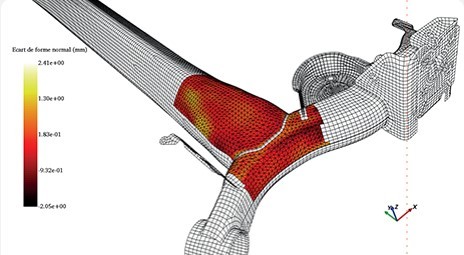
Technical Principles
- Image processing based on finite element mesh (stereo mesh DIC technology).
- Automatic calibration around the mesh.
- Multi-view (no technical limit on the number of cameras).
Next, please refer to the actual application case of EikoSim's multi-camera stereo DIC strain measurement system at MBDA.
UsageStereo DICDisplacement tracking
Preset experiment
The machine with the engine cover to be tested is located in a relatively crowded laboratory. Due to the engine cover being embedded in a special tool, the space for operating and placing physical sensors (LVDT, strain gauges) is limited. These limitations also reduce the effective field of view of the cameras and the space for placing cameras around the parts. To overcome this issue, EikoSim used the EikoTwin virtual tool to virtually construct the experimental plan. This tool simulates the test scene and predicts the camera positions for different areas of interest before the compressive load test (Figure 2).

Figure 2: EikoTwin Virtual predicts the position of the camera system.
Using EikoTwin Virtual, we can predict the camera positions and determine the appropriate size of the speckle spots based on the test specifications (considering camera performance, the distance between the camera and the engine cover, and the refinement of the mesh). The software provides virtual images as close as possible to what is required for real testing (Figure 3).

Figure 3: Virtual images taken during the preset experiment.
With the help of virtual images from the experiment, the preset work can determine the expected minimum uncertainty for displacement measurement in this configuration. This is the experimental measurement noise calculated under ideal conditions, below which displacement cannot be measured. For the two areas of interest, the minimum expected measurement uncertainty for this test is shown in Table 1. This data is interesting because it allows us to precisely limit the quality of future measurements and predict whether the expected measurement accuracy for a given experiment is compatible with the actual conditions of the experiment. In fact, the quantification of uncertainty in stereo DIC measurements is very different from the measurement uncertainty of traditional sensors.
| Measurement Object |
Uncertainty (µm) |
| XAxis Average |
5.8 |
| YAxis Average |
9 |
| ZAxis Average |
9.8 |
Table 1: Average uncertainty obtained from the preset experiment.
Experimental Implementation Process
According to the experimental configuration defined during the preset period, we placed two pairs of static cameras (one image/second, 4112×3008 pixels) to observe areas 1 and 2 respectively.
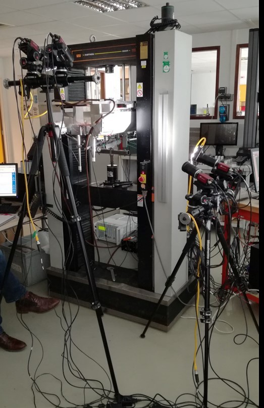
Figure 4: Experimental setup of the multi-camera system.
Due to the use of the image acquisition software EikoTwin VISION, images of the two areas of interest were taken simultaneously during the compressive load test of the engine cover using the multi-camera system (see Figure 5). MBDA performed several types of pressure loading on the engine cover.

Figure 5: Images of the two areas of interest taken during the test.
Results and Outlook
The finite element model of the structure is extremely complex and detailed, and only the areas of interest were selected for experimental measurement. Displacement was measured only in these two areas (the green areas in Figure 6) and compared the measured results with the calculated results.

Figure 6: Defining areas of interest directly on the finite element mesh.
Based on the test images,EikoTwin DIC softwareFor the two areas of interest for MBDA, directly measure the displacements at the nodes of the finite element model provided. The DIC measurement results are displayed on the grid model, allowing for direct comparison with the predictions of the finite element model and the physical sensors that may exist during testing.
Figure 7 shows the comparison of the displacement field from DIC measurements on the part surface in area 1 and the displacement field from digital simulation. It can be seen that the two obtained fields have a strong similarity. The DIC measurement field appears to have a more symmetrical displacement distribution around the center of the part, while the simulated prediction shows a stronger and more dispersed displacement from the center to the engine hood ear.
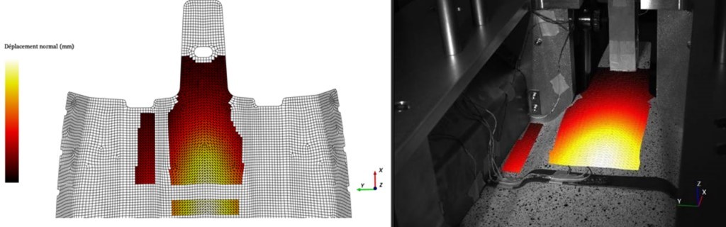
Figure 7: Normal displacement field from DIC in area 1 (left) and normal displacement field from numerical simulation (right)

Figure 8: Z-axis displacement field in area 2
The above Figure 8 shows the Z-axis measured displacement field in area 2. Using EikoTwin DIC, the displacement fields from simulation and actual measurements can also be directly compared for differences, with the difference field showing the deviation between the measured field and the simulated field in the area of interest.
For area 2, the result is shown in Figure 9. It is noteworthy that the difference field here is very noisy, indicating that there is no significant difference between the two fields, or that the displacement changes occurring in one field were not detected in the other field. If MBDA notices differences between the sensor measurements, the stereo DIC measurements, and the simulated values, these differences would not lead to serious consequences, as the DIC field can recalibrate the simulation more effectively, accurately, and broadly than physical sensors.

Figure 9: Difference field between measurements and simulation, directly represented on the finite element grid
Conclusion
MBDAInvested in the acquisition of cameras to implement DIC technology in its measurement panels. To facilitate the integration of DIC measurements into MBDA's workflow, EikoSim assisted as a partner in enhancing MBDA's testing services and design office capabilities. To achieve this, digital image correlation tools (hardware and software) have been piloted in various tests, with increasing complexity from samples and specimens to full structural tests (compression load tests conducted under multi-camera stereo DIC system monitoring).
With the help of EikoTwin Virtual software, virtual experimental presets were made for the actual testing experiments, camera positioning, and speckle implementation, allowing for prior deployment and design. This preliminary research also enabled us to understand the average measurement uncertainty. Using a multi-camera system and EikoTwin VISION software, test data was collected in two different areas of the engine hood as the subject of study. After training the team with EikoSim, MBDA internally processed the obtained images using the digital image correlation software EikoTwin DIC.
Multi-camera DIC setup,Complex strain measurement,Three-dimensional grid DIC,DIC Experiment,EikoTwin DIC,Full-field strain measurement