


Revealing the secrets || Calibration process of multiple material parameters when testing with the EikoTwin DIC strain measurement system.
Release time:
2024-11-21 09:20
Source:
Author: Florent Mathieu-Eiko, CEO of EikoSim
Images and data: Provided by IRT St Exupéry
How to calibrate multiple material parameters through a single test? Here is the guide.
In previous articles, we explored and demonstrated how to measure complex lattice structure movements using digital image correlation technology. This article shows the comparison between measured and simulated displacement fields.

Figure 1
In practice, we often face situations where the simulation model is not directly validated by measurements on the prototype. The sources of errors leading to discrepancies are:
♦ Selection of behavioral laws or material parameters: Even if the laws have been validated in material testing, they may exceed their validity range when we turn to calculations of structures or substructures.
♦ Simulation geometry: The choice of simplified geometry or mesh may explain differences in behavior. For example, differences in wall thickness or local manufacturing defects compared to the CAD model.
♦ Selection of boundary conditions: It is very common to use simplified assumptions (such as zero displacement, displacement, or force acting completely in one direction in space) when establishing model boundary conditions. Reminder: True fixed conditions do not exist!
♦ Selection of contact models: Similarly, preliminary approximations of contact between two parts for simplification or to reduce computational costs may later prove problematic.
Our experience shows that in structural calculations, as in material testing, boundary conditions can play a primary role: therefore, it is necessary to consider them; otherwise, completely incorrect material law parameters may be obtained! In the previously introduced lattice structure testing case, we used EikoTwin digital twin software, and below we will show how to consider these factors during material calibration. This work was conducted in collaboration with IRT Saint Exupéry and is part of the LASER project (2019-2021, supported by PIA - "Future Investment Program", with partners including Safran, Ariane Group, Thales Alenia Space, Altran Technologies, and SIMAP).
A simple test?
The test discussed here is a non-standard test on a BCCZ crystal structure sample (see Figure 2) that lies between shear and embedded free bending. The elements on both sides of the sample are used to fix the structure, while the rigid plate on the right side of the photo applies bending or shear stress to the structure by moving, depending on its length.
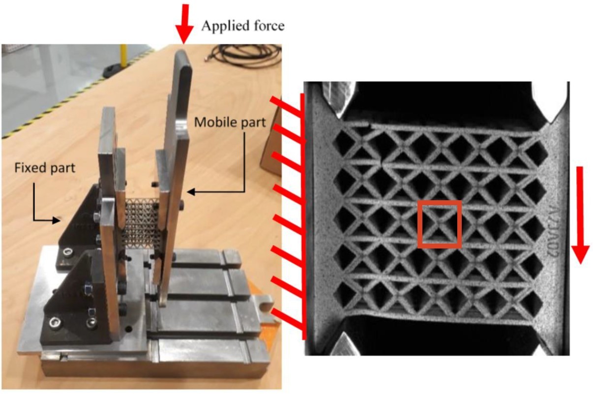 Figure 2
At the end of the previous article, there was a noticeable difference between the measured and simulated displacement fields, as shown in Figure 3. This exaggeration (magnified 15 times here) reveals the differences in kinematics between the physical prototype surface (measurement, green) and the virtual prototype (simulation, red). The loading direction is shown in blue on the screen. This figure shows that as the motion progresses, there is a larger displacement at the bottom of the sample, and rotation also occurs (shear appears less significant and more localized).

Figure 3
Using EikoTwin digital twin software, these situations can be considered simultaneously, and the relevant simulation model can be directly modified. By selecting areas, a set of nodes can be recreated on the model body and applied to the measurement of surface displacements, which we refer to as "enhanced simulation model."
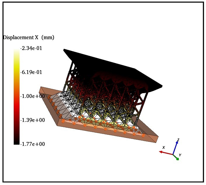
Figure 4 Creation of node set
Ultimately, we can achieve better consistency between simulation and measurement, as shown in Figure 5. The purpose of this test is to identify this model error, which is often hastily mistaken for a defect in the material law.
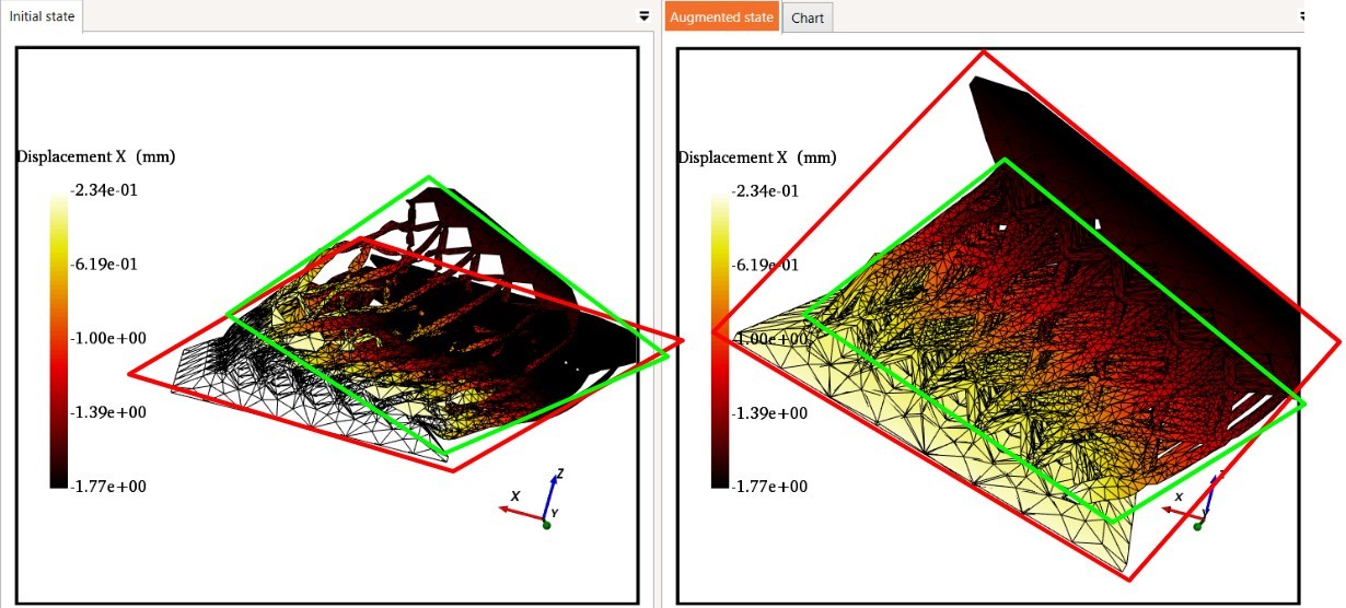
Figure 5
Sensitivity study
After adjusting the boundary conditions, material parameters can be identified. In the digital twin, this identification is based on a sensitivity study of the simulation to model parameters. Here, these parameters are the parameters of the behavioral laws, but other parameters can also be used in the software.
After resetting the boundary conditions, we can see significant differences between the reaction force signal (extracted from the simulation, driven by the newly formed boundary conditions) and the measured force (see below).

Figure 6
The software then calculates the sensitivity of the simulation to the considered parameters (here, the parameters of the elastoplastic power law). A byproduct of this analysis is the creation of sensitivity signals for the test and computational deviation functions based on the selected criteria. In this case, it is a combination of force and displacement fields.
Figure 7 shows, for example, the sensitivity of force to a 5% change in Young's modulus. These signals are then combined to create a unique problem that minimizes the test-computation deviation. Figure 7 also shows the correlation between parameters, which helps to determine the coupling that exists between these parameters in terms of these criteria.

Figure 7
Material parameter calibration
After completing these analyses, identifiable parameters are determined. The iterative algorithm is then responsible for minimizing the test-computation deviation, both in terms of displacement and force. As shown in Figure 8, the error in force predominates here (displacement is well controlled due to the boundary conditions of the measurement). The digital twin algorithm allows us to quickly approach the minimization solution. The evolution of the parameters considered in the analysis and their final values can then be observed.

Figure 8
Once the algorithm converges, we can also observe that the results of the optimized simulation match perfectly with the measurement results (as shown in Figure 9):

Figure 9
As an original application of the digital twin, in this case, we were able to directly identify four parameters of a complex structure, which would require very complex operations if traditional measurement techniques were used without understanding the actual boundary conditions of the structure.
This type of example also answers the classic question: Can we do without physical testing? Of course, the characterization of materials and lattice geometry raises questions, but we can imagine eventually being able to cope with characterization activities for all material and structural combinations. On the other hand, considering this example, it is questionable to represent a structure without a thorough understanding of its boundary conditions, which is often more complex than the calibration of material properties.
In the application presented in this article, the materials discussed are presented in the form of "structures," combining the behavior of materials and their structural components. This allows for the combination of these influences and their characterization in a single test.
Digital Twin,DIC Strain Measurement,EikoTwin DIC,Comparison and validation of simulation models,Simulation measurement comparison,Optical Strain Measurement,Material Parameter Identification